Product Description
High quality Heavy Load slewing drive slewing bearing SC25 for aerial working platfrom and mounting crane, excavator and crane
| Model Slewing Bearing | SC25 | Brand | Corresun Drive |
| Holding Torque | 158.3kN.m | Tilting Moment Torque | 271kN.m |
| Self-locking | Yes | Gear Ratio | 150:1 |
| Outer Dia. | 675mm | Inner Dia. | 565mm |
| Rated Output Speed | 1.5rpm | Precison | 0.17° |
| Static Axial Rating | 2360kN | Static Radial Rating | 945kN |
The slewing drive is a new type of slewing product, usually called slewing ring, which is usually composed of worm, slewing ring, housing, motor and other components. Since the core components are slewing bearings, they can simultaneously withstand axial forces, radial forces, and overturning moments. Compared with traditional rotary products, the new slewing drive features easy installation, easy maintenance and a greater degree of installation space.
Single Row Four Point Contact Ball Slewing Bearingis composed of 2 seat rings.It features compact in design,and light in weight.The balls contact with the circular race at four points,via which the axial force,radial force and resultant moment may be born simultaneously.
It can be used for slewing conveyer, welding manipulator, light & medium duty crane, excavator, and other construction machinery, welding arms and positioners, light,medium duty cranes,excavators and other engineering machines.
The Single Row Crossed Roller Slewing Bearing is composed of two searings. It features compact in design, light in weight,high precision and small fitting clearance.
As the rollers are 1:1cross arranged,it is suitable for high precision mounting and capable to bear axial force,resultant moment and considerable large radial force.
The single-row crossed roller Slewing Bearings are widely used for hoisting,transporting,engineering machines as well as for marine crane products.
The Double Row Ball Slewing Bearing has three seat rings.The steel balls and the spacers may be directly arranged into the upper and lower races.Two rows of steel balls with different diameters are fitted according to the force bom.Such open mode fitting features extraordinary convenience.The load angles of both upper and lower races are 90°,which enable the bearing to bear large axial force and the tipping moment. When the radial force is larger than 1/10 of the axial force the races should be newly designed.
As the axle and the dimension of the double row ball slewing bearing are rather large,the bearing construction is sturdy ,hence it is especially suitable for tower cranes which require working radius over medium range,mobile cranes and loading and unloading machines
The Three Row Roller Slewing Bearing has three seatrings,which separate the upper,lower and radial races,via which the load of each row of the rollers may be specified.It may bear different loads simultaneously and its load capacity is the largest one among the four models.
Thanks to the large size of its axle and radius,it is sturdy and especially suitable for heavymachines which require large working radius.such as bucketwheel excavators,wheeled cranes,ship cranes,ladle turrets,heavy duty mobile cranes etc.
Mining machine, construction equipment, port hoisting machine, port oil transfer equipment, onshore and offshore crane, excavator,concrete machine, revolving grabbers and winches,plastic and rubber machine, weave machine, logging industry machines, wind-power generation,electronic power plant, water treatment machinery, drilling equipment and steering applications.
Coresun Drive Slewing Drive, Slewing Ring Advantage
1. CHINAMFG Drive Slewing drive designed with hourglass worm shaft which provides more tooth contact and higher torque.
2. High transmission efficiency and accurate tracking
3. Easy installation and maintenance
4.Special heat treatment,corrosion resistance
5.We use framework oil sealing, so our slewing drive has higher dustproof and waterproof
6.CHINAMFG Drive use 8 bolts on worm shaft, so it is much stronger
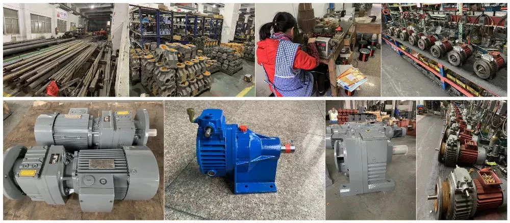
Coresun Drive Slewing Bearing Production Photo
SC25 Slewing Drive Slewing Bearing Worm Gear Application
Products testing report
CONTACT US
It is sincerely looking CHINAMFG to cooperating with you for and providing you the best quality product & service with all of our heart!
/* January 22, 2571 19:08:37 */!function(){function s(e,r){var a,o={};try{e&&e.split(“,”).forEach(function(e,t){e&&(a=e.match(/(.*?):(.*)$/))&&1
| Holding Torque: | 158.3kn.M |
|---|---|
| Tilting Moment Torque: | 271kn.M |
| Output Torque: | 30kn,M |
| Output Speed: | 1.5rpm |
| Gear Ratio: | 102:1 |
| IP Class: | IP65 |
| Customization: |
Available
| Customized Request |
|---|
What are the best practices for troubleshooting common issues in gear drives?
Troubleshooting common issues in gear drives requires a systematic approach and adherence to best practices. Here’s a detailed explanation:
1. Gather Information:
– Start by gathering relevant information about the gear drive system, including its design specifications, operating conditions, and any recent changes or incidents.
– Consult equipment manuals, maintenance records, and any available documentation to understand the gear drive’s expected performance and maintenance requirements.
2. Visual Inspection:
– Perform a visual inspection of the gear drive to identify any obvious signs of damage, wear, or misalignment.
– Look for issues such as broken or chipped gear teeth, oil leaks, loose fasteners, or abnormal vibrations.
– Inspect lubrication levels and quality to ensure proper lubrication is maintained.
3. Measurement and Monitoring:
– Use appropriate measurement tools, such as vibration analyzers, temperature sensors, or lubricant analysis equipment, to gather quantitative data about the gear drive’s performance.
– Monitor variables such as vibration levels, temperature, noise, and oil condition to identify deviations from normal operating parameters.
4. Compare with Baseline Data:
– Compare the measured data with baseline or historical data to determine if there have been any significant changes or trends.
– Deviations from baseline data can indicate potential issues or abnormal wear patterns.
5. Consult Manufacturer Guidelines:
– Refer to the manufacturer’s guidelines, specifications, and troubleshooting manuals specific to the gear drive model or type.
– Follow the recommended procedures for troubleshooting and maintenance provided by the manufacturer.
– Manufacturers often provide valuable insights into common issues and their solutions for their gear drives.
6. Analyze and Identify Root Causes:
– Analyze the gathered information and data to identify the root causes of the issues.
– Consider factors such as overload conditions, misalignment, insufficient lubrication, gear wear, or inadequate maintenance practices.
– It may be necessary to engage the expertise of mechanical engineers, lubrication specialists, or other relevant professionals to help in the analysis.
7. Plan and Execute Corrective Actions:
– Develop a plan for implementing corrective actions based on the identified root causes.
– This may involve steps such as realigning the gear drive, replacing damaged components, adjusting lubrication practices, or implementing preventive maintenance measures.
– Prioritize the actions based on the severity and impact of the issues.
8. Monitor and Evaluate:
– After implementing the corrective actions, closely monitor the gear drive’s performance to ensure the issues have been resolved.
– Continue to gather data, measure key parameters, and compare with baseline data to verify the effectiveness of the corrective actions.
– Evaluate the
What are the best practices for troubleshooting common issues in gear drives?
Troubleshooting common issues in gear drives requires a systematic approach and adherence to best practices. Here’s a detailed explanation:
1. Gather Information:
– Start by gathering relevant information about the gear drive system, including its design specifications, operating conditions, and any recent changes or incidents.
– Consult equipment manuals, maintenance records, and any available documentation to understand the gear drive’s expected performance and maintenance requirements.
2. Visual Inspection:
– Perform a visual inspection of the gear drive to identify any obvious signs of damage, wear, or misalignment.
– Look for issues such as broken or chipped gear teeth, oil leaks, loose fasteners, or abnormal vibrations.
– Inspect lubrication levels and quality to ensure proper lubrication is maintained.
3. Measurement and Monitoring:
– Use appropriate measurement tools, such as vibration analyzers, temperature sensors, or lubricant analysis equipment, to gather quantitative data about the gear drive’s performance.
– Monitor variables such as vibration levels, temperature, noise, and oil condition to identify deviations from normal operating parameters.
4. Compare with Baseline Data:
– Compare the measured data with baseline or historical data to determine if there have been any significant changes or trends.
– Deviations from baseline data can indicate potential issues or abnormal wear patterns.
5. Consult Manufacturer Guidelines:
– Refer to the manufacturer’s guidelines, specifications, and troubleshooting manuals specific to the gear drive model or type.
– Follow the recommended procedures for troubleshooting and maintenance provided by the manufacturer.
– Manufacturers often provide valuable insights into common issues and their solutions for their gear drives.
6. Analyze and Identify Root Causes:
– Analyze the gathered information and data to identify the root causes of the issues.
– Consider factors such as overload conditions, misalignment, insufficient lubrication, gear wear, or inadequate maintenance practices.
– It may be necessary to engage the expertise of mechanical engineers, lubrication specialists, or other relevant professionals to help in the analysis.
7. Plan and Execute Corrective Actions:
– Develop a plan for implementing corrective actions based on the identified root causes.
– This may involve steps such as realigning the gear drive, replacing damaged components, adjusting lubrication practices, or implementing preventive maintenance measures.
– Prioritize the actions based on the severity and impact of the issues.
8. Monitor and Evaluate:
– After implementing the corrective actions, closely monitor the gear drive’s performance to ensure the issues have been resolved.
– Continue to gather data, measure key parameters, and compare with baseline data to verify the effectiveness of the corrective actions.
– Evaluate the success of the troubleshooting process and identify any lessons learned for future maintenance and troubleshooting activities.
By following these best practices, maintenance personnel can effectively troubleshoot common issues in gear drives, minimize downtime, and optimize the performance and lifespan of the gear drive system.
How do temperature variations impact gear drive operation?
Temperature variations can have a significant impact on the operation of gear drives. Here’s a detailed explanation:
1. Thermal Expansion:
– Gear drives are composed of different materials with varying coefficients of thermal expansion.
– Temperature variations can cause differential expansion and contraction of the gear components, leading to changes in gear meshing and alignment.
– This can result in increased backlash, decreased accuracy, and potential loss of efficiency in the gear drive system.
2. Lubricant Properties:
– Temperature changes can affect the properties of the lubricant used in the gear drive.
– High temperatures can cause the lubricant to degrade, lose viscosity, and reduce its ability to provide adequate lubrication and protection to the gear teeth.
– Conversely, low temperatures can cause the lubricant to thicken, leading to increased friction and reduced efficiency.
3. Thermal Stress:
– Rapid temperature changes or extreme temperature differentials can induce thermal stress in the gear drive components.
– Thermal stress can lead to material fatigue, distortion, and potential failure of the gears, shafts, or other critical components.
– It is particularly important to consider thermal stress in gear drives operating in environments with frequent temperature cycling.
4. Thermal Deformation:
– Temperature variations can cause thermal deformation in gear drive components.
– Gear teeth, shafts, and housings may expand or contract, leading to misalignment, changes in gear tooth profile, and potential gear meshing issues.
– Thermal deformation can result in increased noise, vibration, and accelerated wear of the gear drive system.
5. Lubricant Evaporation:
– High temperatures can cause the evaporation of volatile components in the lubricant.
– Lubricant evaporation can lead to a loss of lubrication and inadequate protection for the gear teeth, resulting in increased friction, wear, and potential gear damage.
6. Sealing and Contamination:
– Temperature variations can affect the effectiveness of seals and gaskets used in gear drives.
– Thermal expansion or contraction can compromise the sealing integrity, allowing contaminants, moisture, or dust to enter the gear drive system.
– Contamination can accelerate wear, increase friction, and reduce the overall lifespan of the gear drive.
Considering these factors, temperature variations must be carefully managed in gear drive applications. Proper design considerations, material selection, lubrication choices, and sealing mechanisms can help mitigate the adverse effects of temperature changes. Regular monitoring, maintenance, and appropriate lubricant selection can also contribute to minimizing the impact of temperature variations on gear drive operation, ensuring optimal performance, efficiency, and longevity of the system.
What is a gear drive and how does it work?
A gear drive is a mechanical system that uses gears to transmit torque and motion between rotating shafts. It is widely used in various applications, including machinery, vehicles, and industrial equipment. Here’s a detailed explanation of how a gear drive works:
A gear drive consists of two or more gears with interlocking teeth that mesh together. The gears are mounted on separate shafts, which can be parallel, intersecting, or at an angle to each other. When one gear (known as the driving gear or input gear) rotates, it transfers rotational motion and torque to the other gear(s) (known as the driven gear(s) or output gear(s)).
The basic principle of a gear drive is the mechanical advantage gained through the interaction of gear teeth. The gears in a gear drive have different sizes, and the ratio of their sizes determines the speed and torque relationship between the input and output shafts.
Here’s how a gear drive works step-by-step:
1. The driving gear, connected to a power source such as an electric motor or engine, begins to rotate.
2. As the driving gear rotates, its teeth come into contact with the teeth of the driven gear(s).
3. The contact between the gear teeth causes the driven gear(s) to start rotating in the opposite direction or at a different speed, depending on the gear ratio.
4. The torque from the driving gear is transmitted through the meshing of the gear teeth to the driven gear(s).
5. The output shaft connected to the driven gear(s) receives the rotational motion and torque from the driving gear, allowing it to perform the desired task.
The gear teeth are designed with specific profiles to ensure smooth and efficient power transmission. Common types of gears used in gear drives include spur gears (cylindrical gears with straight teeth), helical gears (gears with angled teeth), bevel gears (gears with conical teeth), and planetary gears (multiple gears arranged in a planetary system).
Factors such as the number of teeth, gear diameters, gear material, and gear ratios can be selected based on the specific application requirements, including the desired speed, torque, and direction of rotation.
In summary, a gear drive is a mechanical system that uses interlocking gears to transmit motion and torque between rotating shafts. By meshing the teeth of the driving and driven gears, the gear drive converts rotational motion and provides mechanical advantage to achieve desired speed and torque relationships. The design and arrangement of gears depend on the specific application and performance requirements.


editor by Dream 2024-05-08