Product Description
Product Description:
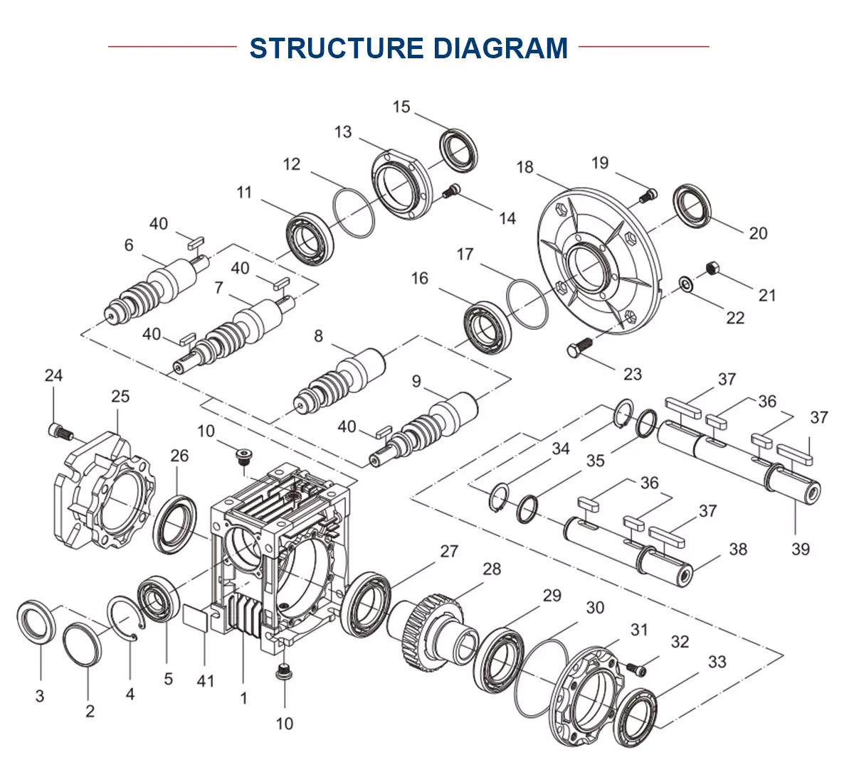
1.Flexspline is a hollow flanging standard cylinder structure.
2.There is a large-diameter hollow shaft hole in the middle of the cam of the wave generator. The internal design of the reducer has a support bearing.
3.It has a fully sealed structure and is easy to install. It is very suitable for the occasions where the wire needs to be threaded from the center of the reducer.
Advantages:
The first:High precision,high torque
The second:dedicated technical personnel can be on-the-go to provide design solutions
The third:Factory direct sales fine workmanship durable quality assurance
The fourth:Product quality issues have a one-year warranty time, can be returned for replacement or repair
Company profile:
HangZhou CHINAMFG Technology Co., Ltd. established in 2014, is committed to the R & D plant of high-precision transmission components. At present, the annual production capacity can reach 45000 sets of harmonic reducers. We firmly believe in quality first. All links from raw materials to finished products are strictly supervised and controlled, which provides a CHINAMFG foundation for product quality. Our products are sold all over the country and abroad.
The harmonic reducer and other high-precision transmission components were independently developed by the company. Our company spends 20% of its sales every year on the research and development of new technologies in the industry. There are 5 people in R & D.
Our advantage is as below:
1.7 years of marketing experience
2. 5-person R & D team to provide you with technical support
3. It is sold at home and abroad and exported to Turkey and Ireland
4. The product quality is guaranteed with a one-year warranty
5. Products can be customized
Strength factory:
Our plant has an entire campus The number of workshops is around 300 Whether it’s from the production of raw materials and the procurement of raw materials to the inspection of finished products, we’re doing it ourselves. There is a complete production system
HST-III Parameter:
| Model | Speed ratio | Enter the rated torque at 2000r/min | Allowed CHINAMFG torque at start stop | The allowable maximum of the average load torque | Maximum torque is allowed in an instant | Allow the maximum speed to be entered | Average input speed is allowed | Back gap | design life | ||||
| NM | kgfm | NM | kgfm | NM | kgfm | NM | kgfm | r / min | r / min | Arc sec | Hour | ||
| 14 | 50 | 6.2 | 0.6 | 20.7 | 2.1 | 7.9 | 0.7 | 40.3 | 4.1 | 7000 | 3000 | ≤30 | 10000 |
| 80 | 9 | 0.9 | 27 | 2.7 | 12.7 | 1.3 | 54.1 | 5.5 | |||||
| 100 | 9 | 0.9 | 32 | 3.3 | 12.7 | 1.3 | 62.1 | 6.3 | |||||
| 17 | 50 | 18.4 | 1.9 | 39 | 4 | 29.9 | 3 | 80.5 | 8.2 | 6500 | 3000 | ≤30 | 15000 |
| 80 | 25.3 | 2.6 | 49.5 | 5 | 31 | 3.2 | 100.1 | 10.2 | |||||
| 100 | 27.6 | 2.8 | 62 | 6.3 | 45 | 4.6 | 124.2 | 12.7 | |||||
| 20 | 50 | 28.8 | 2.9 | 64.4 | 6.6 | 39 | 4 | 112.7 | 11.5 | 5600 | 3000 | ≤30 | 15000 |
| 80 | 39.1 | 4 | 85 | 8.8 | 54 | 5.5 | 146.1 | 14.9 | |||||
| 100 | 46 | 4.7 | 94.3 | 9.6 | 56 | 5.8 | 169.1 | 17.2 | |||||
| 120 | 46 | 4.7 | 100 | 10.2 | 56 | 5.8 | 169.1 | 17.2 | |||||
| 160 | 46 | 4.7 | 100 | 10.2 | 56 | 5.8 | 169.1 | 17.2 | |||||
| 25 | 50 | 44.9 | 4.6 | 113 | 11.5 | 63 | 6.5 | 213.9 | 21.8 | 4800 | 3000 | ≤30 | 15000 |
| 80 | 72.5 | 7.4 | 158 | 16.1 | 100 | 10.2 | 293.3 | 29.9 | |||||
| 100 | 77.1 | 7.9 | 181 | 18.4 | 124 | 12.7 | 326.6 | 33.3 | |||||
| 120 | 77.1 | 7.9 | 192 | 19.6 | 124 | 12.7 | 349.6 | 35.6 | |||||
| 32 | 50 | 87.4 | 8.9 | 248 | 25.3 | 124 | 12.7 | 439 | 44.8 | 4000 | 3000 | ≤30 | 15000 |
| 80 | 135.7 | 13.8 | 350 | 35.6 | 192 | 19.6 | 653 | 66.6 | |||||
| 100 | 157.6 | 16.1 | 383 | 39.1 | 248 | 25.3 | 744 | 75.9 | |||||
| 40 | 100 | 308 | 37.2 | 660 | 67 | 432 | 44 | 1232 | 126.7 | 4000 | 3000 | ≤30 | 15000 |
HSG Parameter:
| Model | Speed ratio | Enter the rated torque at 2000r/min | Allowed CHINAMFG torque at start stop | The allowable maximum of the average load torque | Maximum torque is allowed in an instant | Allow the maximum speed to be entered | Average input speed is allowed | Back gap | design life | ||||
| NM | kgfm | NM | kgfm | NM | kgfm | NM | kgfm | r / min | r / min | Arc sec | Hour | ||
| 14 | 50 | 7 | 0.7 | 23 | 2.3 | 9 | 0.9 | 46 | 4.7 | 14000 | 8500 | ≤20 | 15000 |
| 80 | 10 | 1 | 30 | 3.1 | 14 | 1.4 | 61 | 6.2 | |||||
| 100 | 10 | 1 | 36 | 3.7 | 14 | 1.4 | 70 | 7.2 | |||||
| 17 | 50 | 21 | 2.1 | 44 | 4.5 | 34 | 3.4 | 91 | 9 | 10000 | 7300 | ≤20 | 20000 |
| 80 | 29 | 2.9 | 56 | 5.7 | 35 | 3.6 | 113 | 12 | |||||
| 100 | 31 | 3.2 | 70 | 7.2 | 51 | 5.2 | 143 | 15 | |||||
| 20 | 50 | 33 | 3.3 | 73 | 7.4 | 44 | 4.5 | 127 | 13 | 10000 | 6500 | ≤20 | 20000 |
| 80 | 44 | 4.5 | 96 | 9.8 | 61 | 6.2 | 165 | 17 | |||||
| 100 | 52 | 5.3 | 107 | 10.9 | 64 | 6.5 | 191 | 20 | |||||
| 120 | 52 | 5.3 | 113 | 11.5 | 64 | 6.5 | 191 | 20 | |||||
| 160 | 52 | 5.3 | 120 | 12.2 | 64 | 6.5 | 191 | 20 | |||||
| 25 | 50 | 51 | 5.2 | 127 | 13 | 72 | 7.3 | 242 | 25 | 7500 | 5600 | ≤20 | 20000 |
| 80 | 82 | 8.4 | 178 | 18 | 113 | 12 | 332 | 34 | |||||
| 100 | 87 | 8.9 | 204 | 21 | 140 | 14 | 369 | 38 | |||||
| 120 | 87 | 8.9 | 217 | 22 | 140 | 14 | 395 | 40 | |||||
| 32 | 50 | 99 | 10 | 281 | 29 | 140 | 14 | 497 | 51 | 7000 | 4800 | ≤20 | 20000 |
| 80 | 153 | 16 | 395 | 40 | 217 | 22 | 738 | 75 | |||||
| 100 | 178 | 18 | 433 | 44 | 281 | 29 | 841 | 86 | |||||
| 40 | 100 | 345 | 35 | 738 | 75 | 484 | 49 | 1400 | 143 | 5600 | 4000 | ≤20 | 20000 |
Exhibition:
Application case:
FQA:
Q: What should I provide when I choose gearbox/speed reducer?
A: The best way is to provide the motor drawing with parameter. Our engineer will check and recommend the most suitable gearbox model for your refer.
Or you can also provide below specification as well:
1) Type, model and torque.
2) Ratio or output speed
3) Working condition and connection method
4) Quality and installed machine name
5) Input mode and input speed
6) Motor brand model or flange and motor shaft size
/* January 22, 2571 19:08:37 */!function(){function s(e,r){var a,o={};try{e&&e.split(“,”).forEach(function(e,t){e&&(a=e.match(/(.*?):(.*)$/))&&1
| Application: | Motor, Machinery, Agricultural Machinery |
|---|---|
| Hardness: | Hardened Tooth Surface |
| Installation: | 90 Degree |
| Layout: | Coaxial |
| Gear Shape: | Cylindrical Gear |
| Step: | Single-Step |
| Samples: |
US$ 100/Piece
1 Piece(Min.Order) | |
|---|
| Customization: |
Available
| Customized Request |
|---|
How do gear drives work in robotic and automated systems?
Gear drives play a crucial role in robotic and automated systems by transmitting motion and power between different components. Here’s a detailed explanation of how gear drives work in these systems:
1. Power Transmission:
– In robotic and automated systems, gear drives are used to transmit power from motors to various mechanical components.
– Electric motors provide rotational motion, which is converted into linear or angular motion by the gear drive.
– The gear drive consists of a set of gears with different sizes and configurations that mesh together to transfer torque and speed.
2. Speed and Torque Conversion:
– Gear drives allow for the conversion of speed and torque between the motor and the driven components.
– By using gears with different sizes (varying number of teeth), the gear drive can change the rotational speed and torque output.
– For example, a gear drive with a larger gear driving a smaller gear will increase the torque while reducing the speed, and vice versa.
3. Motion Control:
– Gear drives enable precise motion control in robotic and automated systems.
– By selecting the appropriate gear ratio, the gear drive can control the speed and position of the driven components.
– Gear drives can be used to achieve smooth and accurate movements, such as in robot arms, conveyor systems, or CNC machines.
4. Reducing Inertia:
– Inertia refers to an object’s resistance to changes in motion.
– Gear drives can help reduce the overall inertia in robotic and automated systems.
– By using smaller gears, the gear drive can reduce the inertia of the driven components, allowing for faster and more responsive movements.
5. Backlash Compensation:
– Backlash refers to the slight play or clearance between gear teeth, which can result in a loss of accuracy and precision.
– Gear drives in robotic and automated systems often incorporate backlash compensation mechanisms to minimize this issue.
– These mechanisms can include preloading the gears or using anti-backlash gears to eliminate or reduce the effects of backlash.
6. Load Distribution:
– In complex robotic systems, multiple gear drives are often used to distribute the load and share the torque among different components.
– This distribution of load helps prevent overloading of individual gear drives and ensures a balanced operation of the system.
7. Redundancy:
– Some robotic and automated systems incorporate redundant gear drives to enhance reliability and fault tolerance.
– Redundant gear drives can provide backup functionality in case of failure or allow for continued operation with reduced performance in the event of a single gear drive failure.
Overall, gear drives are essential components in robotic and automated systems, enabling power transmission, motion control, speed and torque conversion, and load distribution. The specific design and configuration of gear drives in these systems depend on the application requirements, desired performance, and system constraints.
How are gear drives used in renewable energy applications?
Gear drives play a crucial role in various renewable energy applications. Here’s a detailed explanation:
1. Wind Turbines:
– Gear drives are widely used in wind turbines to convert the low-speed rotation of the turbine blades into high-speed rotation suitable for generating electricity.
– The gear drives amplify the rotational speed, allowing the generator to operate at the required speed to produce electricity efficiently.
2. Solar Tracking Systems:
– In solar tracking systems, gear drives are employed to adjust the position of solar panels or mirrors to maximize the capture of solar energy.
– The gear drives enable precise and controlled movement of the panels or mirrors, aligning them with the sun’s position throughout the day for optimal energy collection.
3. Hydroelectric Power Plants:
– Gear drives are utilized in hydroelectric power plants to convert the slow rotational motion of the turbine into high-speed rotation for power generation.
– The gear drives increase the rotational speed and transmit the power to the generator, which converts the mechanical energy into electrical energy.
4. Tidal and Wave Energy Converters:
– Gear drives are employed in tidal and wave energy converters to increase the rotational speed of the turbine or generator system.
– They help convert the relatively slow and irregular motion of the tides or waves into a higher-speed rotation suitable for electricity generation.
5. Geothermal Power Plants:
– Gear drives are utilized in geothermal power plants to transmit power from the geothermal turbine to the generator for electricity production.
– They enable the conversion of the low-speed, high-torque rotational motion of the turbine into high-speed rotation required by the generator.
6. Biomass Energy Systems:
– Gear drives are used in biomass energy systems to convert the rotational motion of the biomass combustion engine or steam turbine into high-speed rotation for electricity generation.
– The gear drives help optimize the rotational speed and torque characteristics of the system for efficient power production.
Overall, gear drives are essential components in renewable energy applications, enabling the efficient conversion of various natural energy sources into usable electricity. They help amplify rotational speed, adjust positions for optimal energy capture, and transmit power from turbines to generators. By facilitating the effective utilization of renewable energy sources, gear drives contribute to the growth and sustainability of clean and renewable energy generation.
How do you calculate the gear ratio in a gear drive?
Calculating the gear ratio in a gear drive involves determining the relationship between the number of teeth on the driving gear (pinion) and the number of teeth on the driven gear. Here’s a detailed explanation:
The gear ratio is defined as the ratio of the number of teeth on the driven gear to the number of teeth on the driving gear. It represents the speed or torque multiplication or reduction achieved by the gear drive.
The gear ratio (GR) can be calculated using the following formula:
GR = Number of teeth on driven gear / Number of teeth on driving gear
For example, consider a gear drive with a driving gear (pinion) having 20 teeth and a driven gear having 60 teeth. The gear ratio can be calculated as follows:
GR = 60 (driven gear) / 20 (driving gear) = 3
In this case, the gear ratio is 3:1, indicating that for every three revolutions of the driving gear, the driven gear completes one revolution. This represents a speed reduction, with the driven gear rotating at one-third the speed of the driving gear.
It’s important to note that the gear ratio can be expressed in different formats, such as a decimal, fraction, or as a ratio. The choice of representation depends on the specific requirements and conventions of the gear drive application.
Additionally, it’s worth mentioning that gear drives can have multiple gears arranged in series or parallel, forming gear trains. In such cases, the overall gear ratio is calculated by multiplying the individual gear ratios of each gear pair in the train.
When designing or selecting gear drives, calculating the gear ratio is essential for determining the speed reduction or increase and torque amplification provided by the gear system. It enables engineers and designers to match the gear drive to the desired operational requirements of the mechanical system.


editor by Dream 2024-04-23